Car Cruise Control System Block Diagram

Block Diagram Of The Cruise Control System Download Scientific Diagram

3 Automobile Cruise Control Vehicle Speed Control Principles Of Operation And Implementation
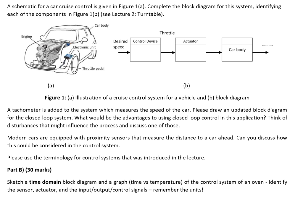
Solved A Schematic For A Car Cruise Control Is Given In F Chegg Com
Http Www Ajer Org Papers V5 06 E050602429 Pdf

Control Tutorials For Matlab And Simulink Cruise Control Frequency Domain Methods For Controller Design

Figure 2 From Modeling And Design Of Cruise Control System With Feedforward For All Terrian Vehicles Semantic Scholar
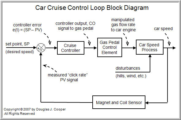
Please see the cruise control.
Car cruise control system block diagram.

Adaptive Cruise Controller Block Diagram Download Scientific Diagram

Pdf Comparison Of Pid Ga And Fuzzy Logic Controllers For Cruise Control System
The Components Of A Control Loop Control Guru
Engineer On A Disk
Source : pinterest.com
